Mikeee Tassinari goes through the step-by-step process of replacing an Atwood jack controller with a new Rieco-Titan jack controller. Somebody hide the label maker.
Mike Tassinari, aka Mikeee, aka the Grand Poobah of the Northeast Truck Camping Jamboree, is well known at TCM HQ for his unpredictable communications.
Now that he has somehow discovered texting, the frequency of these inquiries has intensified. Let’s just say it’s not unusual to receive a surprise, “Call me when you can” message from Mikeee on a Tuesday afternoon.
For reasons only a therapist could interpret, these five words never fail to inspire fearful dread, like being called into the principal’s office. Not that that ever happened, honest!
Instantly I run through everything Mikeee could be on to. How could he know I threw out my fifth-grade report card? Maybe it wasn’t me who spray-painted, “Surrender Dorothy” in the senior parking lot. Look, it’s not even my handwriting.
Ring… ring…
“Ha-low kids! I have an article for your truck camping magazine.”
Whew! Wait, what? First of all, I’m 47 years old. And second, what is he up to this time? Bracing for impact…
“Remember when I replaced all my Atwood jacks with Rieco-Titan jacks?” he asks, not pausing for the answer he already knows since we were (a) there, and (b) published a detailed article about it.
“Well, I have now also replaced the main control board. I took photos and wrote the whole thing up. I’ll send it to you and you tell me what you think. Ta-ta!”
And just like that, Click! and he’s gone. Thank you Mikeee!
by Mikeee Tassinari
As many of you know, Atwood truck camper jacks and control boards are no longer made. Furthermore, the supplies of these products are, at best, becoming more scarce by the day.
This means if your Atwood control board or Atwood jacks stop working, it is getting extremely difficult if not impossible to find replacement Atwood jacks and control boards.
Thankfully, Rieco-Titan Products has stepped up with a controller and jacks that can be used to replace the Atwood components. You can literally remove a single malfunctioning Atwood jack and replace it with a Rieco-Titan jack. Or two jacks, three jacks or four jacks.
For best performance, Rieco-Titan recommends replacing both fronts, both backs, or all four jacks at the same time. That way they will raise and lower your camper at a more even rate.
Rieco-Titan control boards also work with most Atwood corner jacks. In fact, the only Atwood jacks that don’t work with Rieco-Titan control boards are the variety with rocker switches on the jack covers. Those are fairly rare, so chances are your Atwoods are compatible with the Rieco-Titan controller.
This project involves removing an Atwood controller and installing a Rieco-Titan controller in my 2016 Lance 1172. I want to thank Doug Bakker, Operations Manager at Rieco-Titan Products, for helping make this transition as straight-forward as possible.
The Rieco-Titan control board is approximately 2-inches wider than the outgoing Atwood control board, and will not fit in the same spot. It was possible to use the same space, but I would have had to move two large neutral bus bars with lots of wires attached to them.
After looking at the time and labor to relocate the two neutral bus bars and the wires connected to them, I decided it would be easier to just relocate the new Rieco-Titan circuit board to another location.
The factory-installed Atwood control board was located in the very front of my truck camper. The selected location for the new Rieco-Titan control board is under a drawer on the right side of the camper.
I took the old Atwood controller out and ran a wiring harness from where the Atwood had been installed to the new Rieco-Titan controller location. This was a complex task as the control boards needed to control six 12-volt motors. I was however, able to reuse the Atwood wiring.
This required running positive and negative wires to each component, twelve wires in all at 10-gauge wire. I could use 12-gauge wire but opted or 10-gauge to eliminate potential voltage drop issues.
Rather than making a humongous new wiring harness, I made three smaller wire harnesses of four-wires each. I then spiral-wrapped the wires to prevent wire chaffing.
What follows are the in-progress photos showing the various steps to this project.
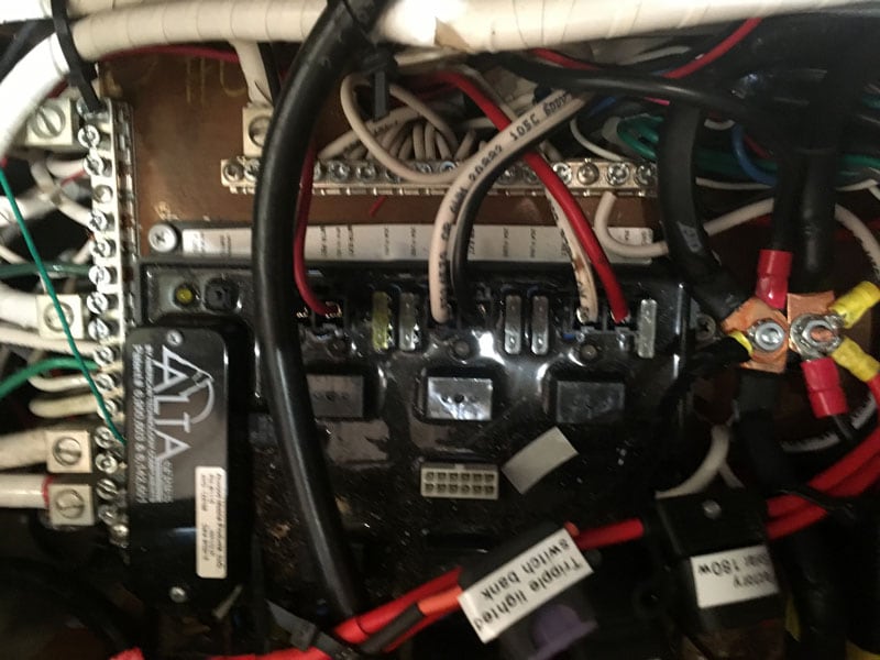
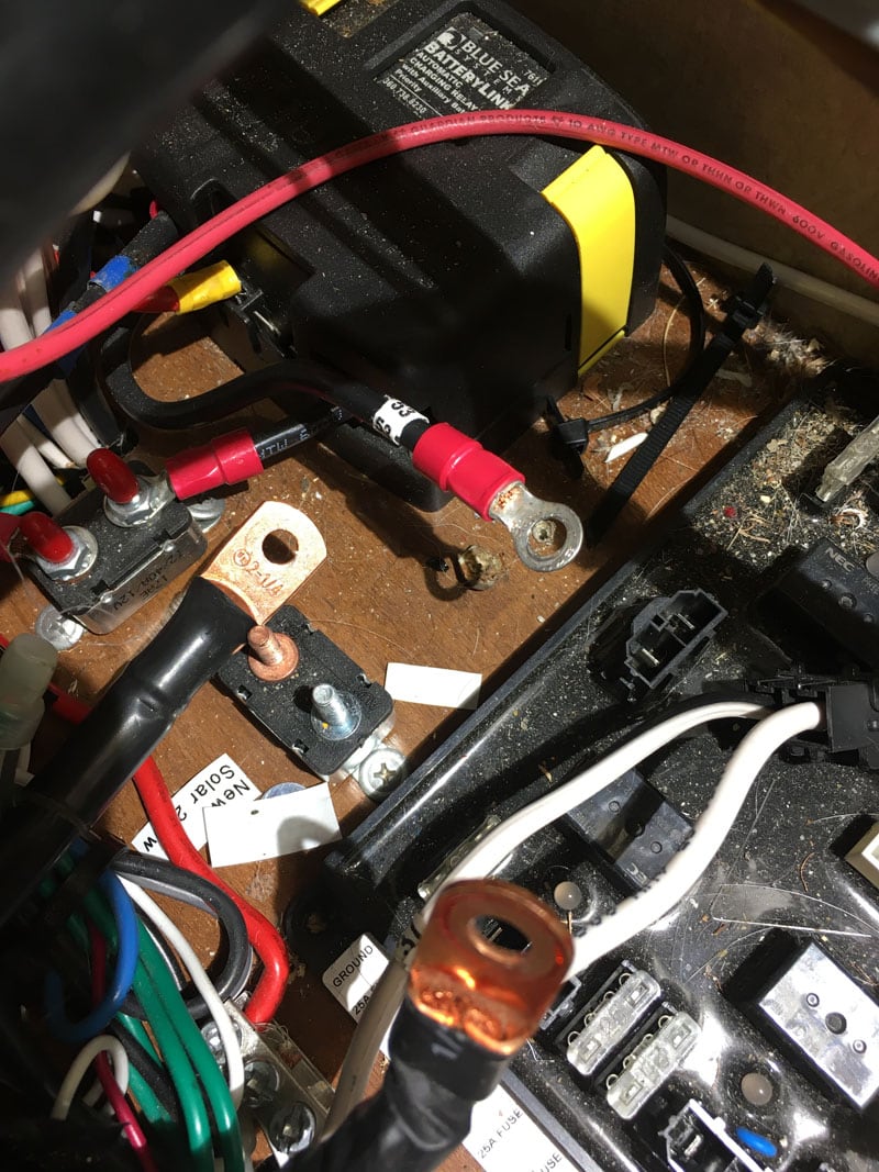
Pictured above is the location of Atwood control board that is being removed. As you can see, the two neutral bus bars on the top and left of this picture prevented me from installing the new Rieco-Titan control board in this location.

This is another shot of the Atwood board buried in a rat’s nest of wires.
In this picture, I am starting to remove wires in and around the Atwood board so that I can remove the board completely. Every wire that was removed had a number attached to it. I kept a log of what device each wire controlled.
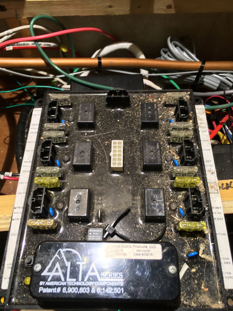
All wires are removed from the Atwood control board.
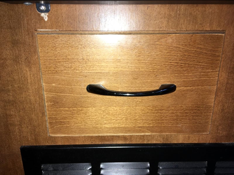
My not so secret location for the placement of the Rieco-Titan control board.
Here is the cavity where my stove and oven sit. We still have to dig deeper to the future location of the Rieco-Titan control board.
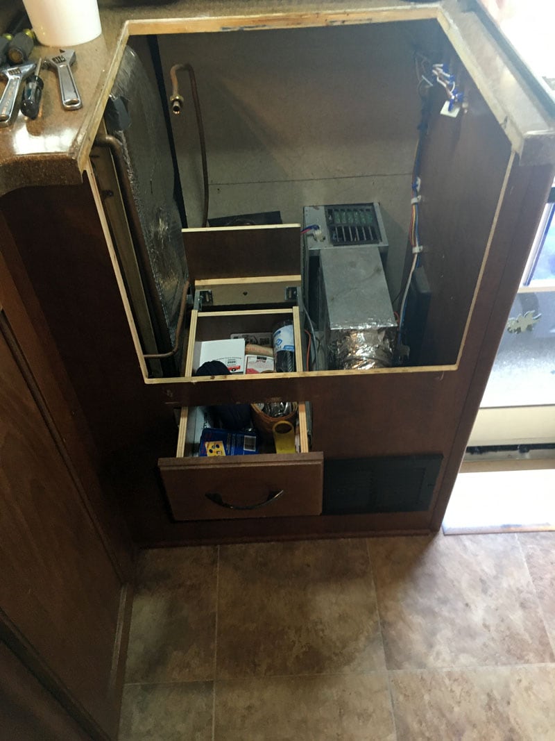
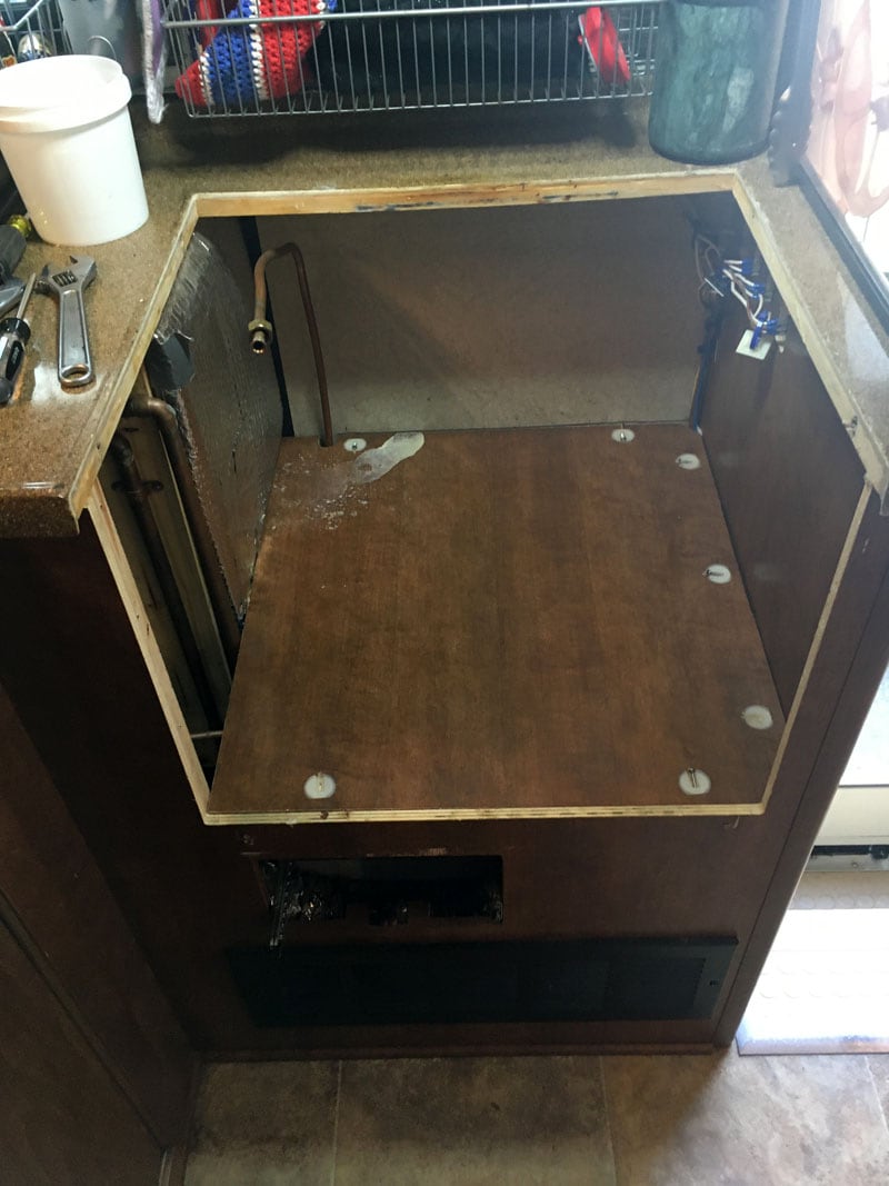
Digging deeper you now see the bottom panel removed below the oven. Still need to dig deeper!
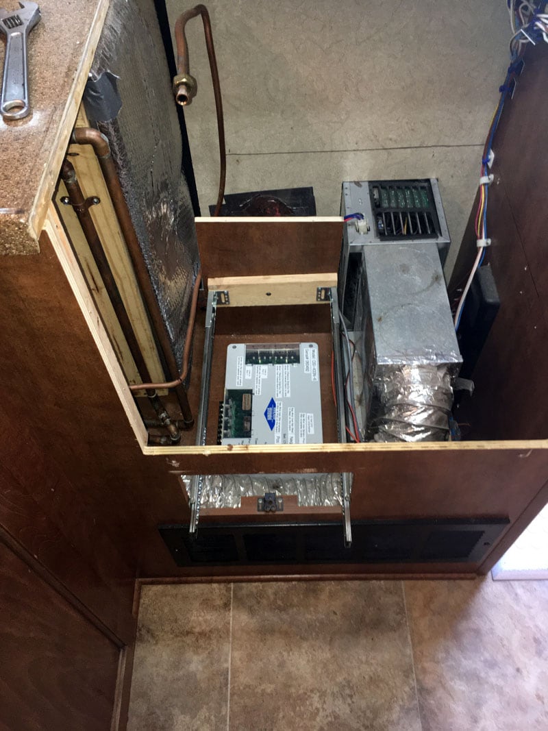
The drawer is removed. Notice the Rieco-Titan control board is tucked below the drawer. This is where I chose to permanently locate the control board.
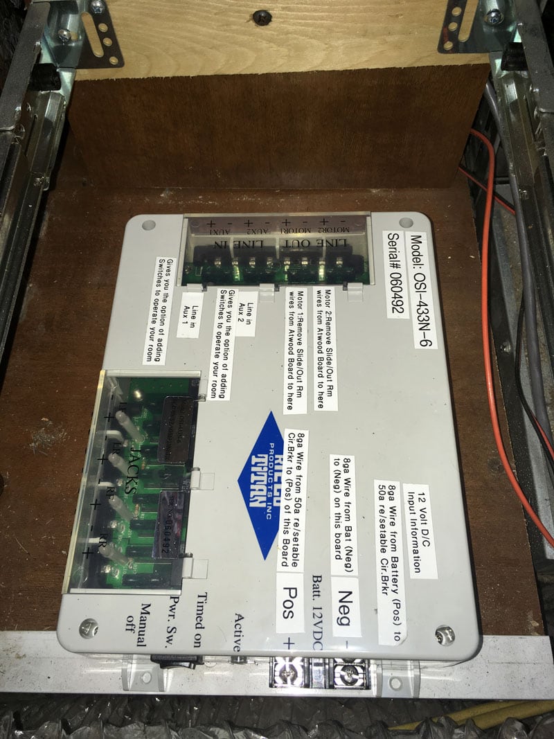
Okay, Okay, Okay. I can hear it now. Ole Mikeee is out of control with his labeler.
Seriously, it has made it much easier to read when one’s eyes are not so hot anymore.
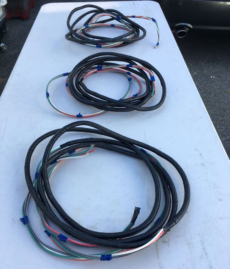
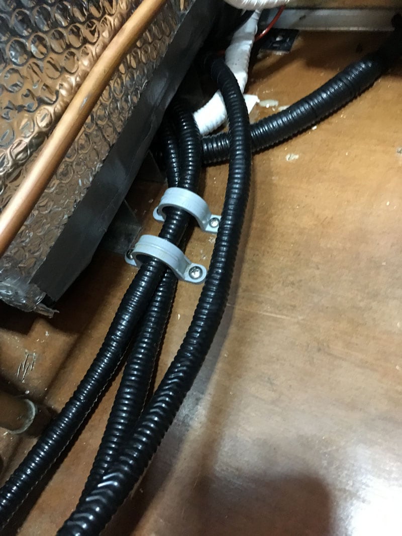
These are the three wiring harnesses I made up to power up the four jacks and two slide-out rooms. Each harness consists of 10-gauge wire with four wires to a harness that is 15-feet long.
Yes, I could have gone with 12-gauge wire, but did not want any voltage drop issues. I ended up using about 12 to 13-feet of harness. I used spiral wrap to protect the wires from a potential chaffing situation.
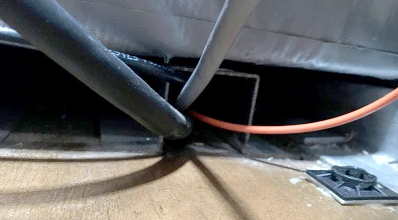
In my sleuthing to find a chase way from the propane stove location to the front of the camper, I found this neat chase way that runs just under the propane tank compartment of my Lance 1172.
In the above picture, you can see the three wiring harnesses I ran.
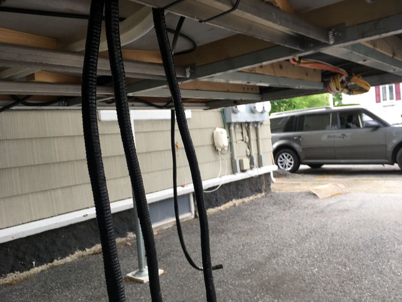
This is the other end of the three wiring harnesses. They will shortly be moved to the forward left compartment where I will be sending down all the connections for the four jacks and two slide-out rooms that were connected to the Atwood control board.
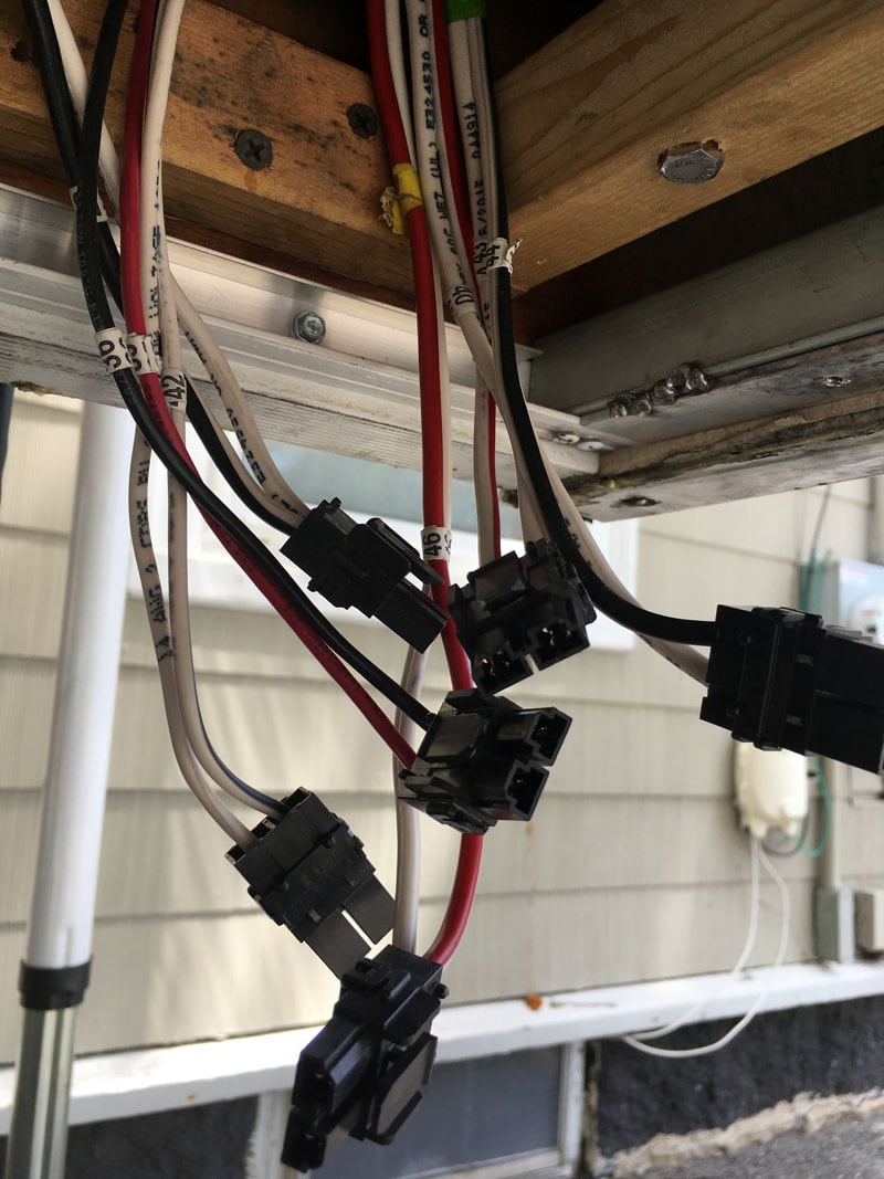
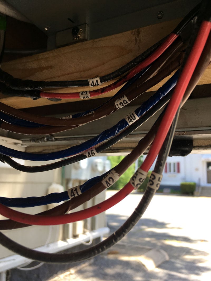
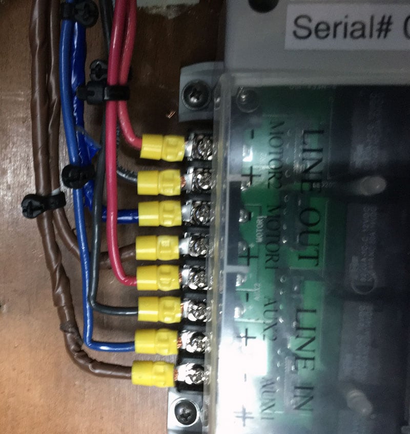
Above you see the six male jack connectors that plugged into the Atwood control board. Look closely and you will see the numbers on the wires to identify what device they came from.
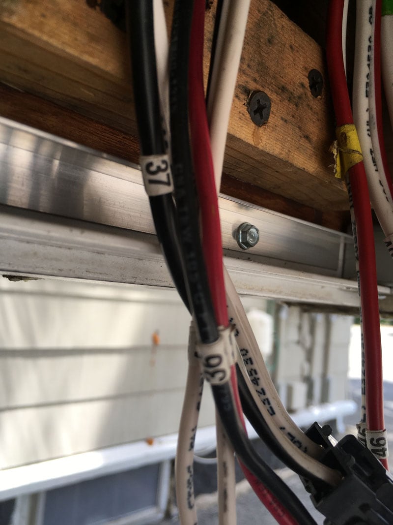
Here is a close up of the wire marker numbers that I used.
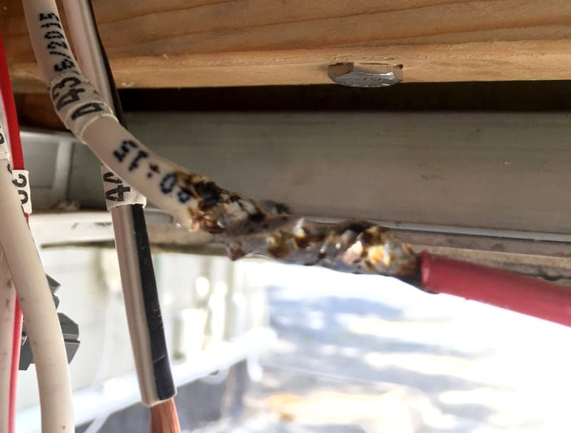
No wire nuts or Scotchloks for Mikeee. Every wire was soldered.
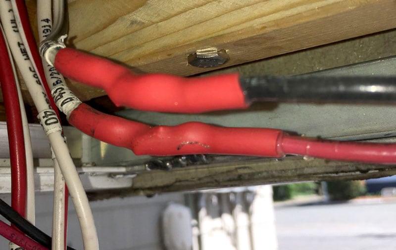
Next came the shrink tube that slides over the soldered wires. What I like about this brand of shrink tube is the glue that’s put on the inside of the tube. It really makes a wicked watertight seal.
Next came the electrical tape that went over the shrink tube.
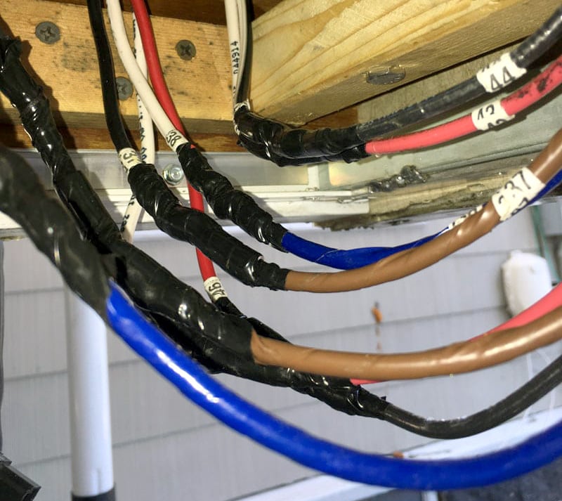
Above is the finished product with all wires and their identifying numbers.
Please note that I incorporated the installation of a 2,000-watt pure sine wave inverter at the same time I installed the Rieco-Titan control board and associated wiring.
Now to power up the Rieco-Titan control board.
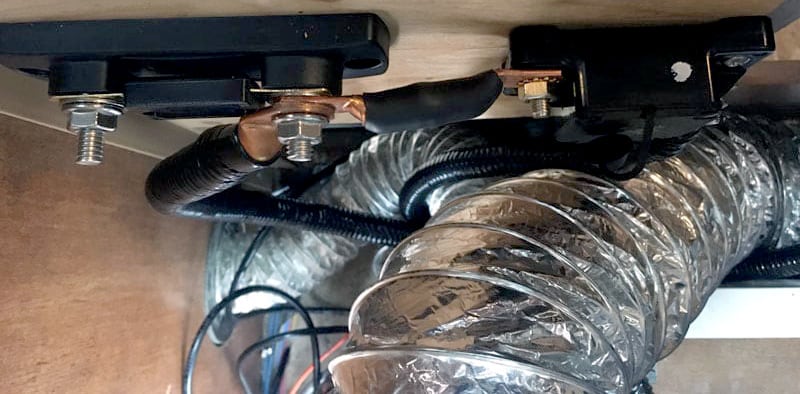
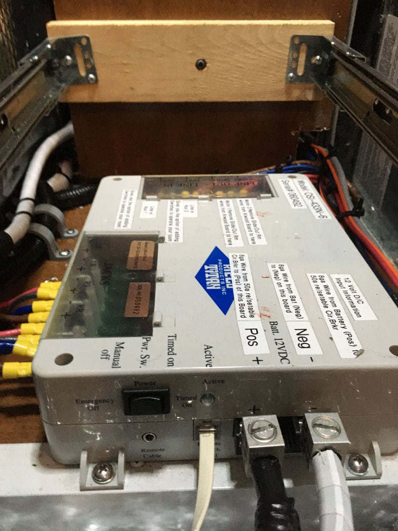
You see two fuses in the above picture. The fuse on the left is the 175A fuse that feeds my inverter. I used 1/0-gauge wire for the inverter project.
The smaller two gauge jumper wire feeds a smaller 50-amp in-line resettable fuse on the right. Rieco-Titan Products requires that you install a 50-amp in-line auto resettable fuse to protect their control board, and that is what I have done.
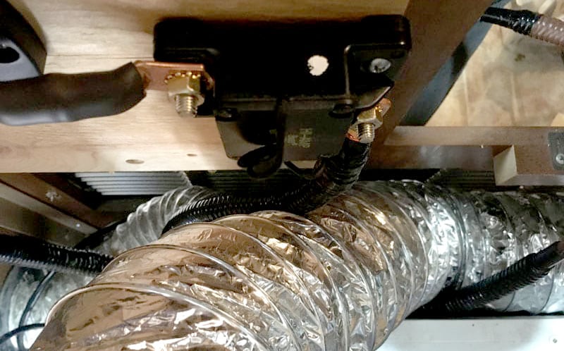
Above is a closer picture of the 50-amp in-line auto resettable fuse that I installed to protect the Rieco-Titan control board.
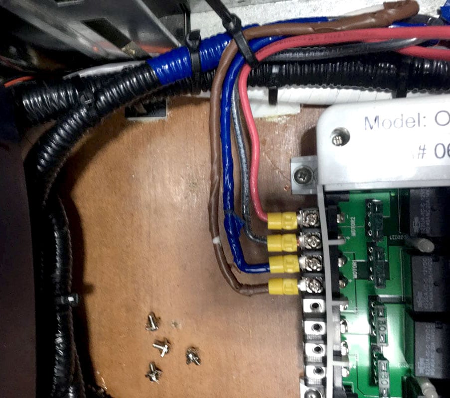
Now the fun part begins. So, I have twelve wires to connect on the Rieco-Titan board. The blue tape in the upper right-hand corner of this picture covering the spiral wrap tells me that I am using the blue wire harness and the color-coded wires for this blue harness. I had run out of wire marker numbers at this point and re-numbered them later in. Here are the first four wires I connected.
You cannot see it in the picture above, but the next four wires originated from the “Brown Wire” harness. Eight wires down and four wires to go! Yipeee!
Not to bore you with every single connection, but you now see all 12 wires that left the Rieco-Titan control board and headed to the front of my camper. They connect to the 12 wires that I removed from the Atwood control board.
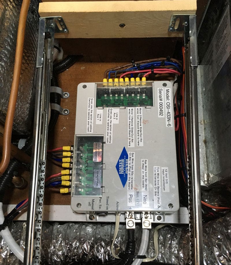
Above is a top view of the Rieco-Titan control board, completely wired. I am sure some of you eagle-eyed people are wondering why in the past pictures I talked about 12 wires and not the 16 wire connections you see in this picture.
Rieco-Titan incorporates a really neat feature in their control board in that you can hardwire two rocker switches to open/close the two slide-out rooms. With this feature, there is no need to use the remote clicker at all. So that accounts for the four other wires you see in this picture.
You can also see the 12-volt DC white and black wires that power up the Rieco-Titan board as well as the two pair of white thin cord that is run to the activation switch.
You will get a better idea of the installation of the activation switch and rocker switches in the next set of pictures.
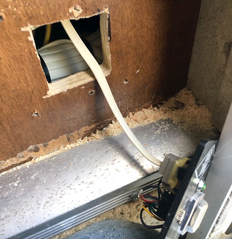
Rieco-Titan products uses an activation switch to wake up the control board. This is the hole I cut out to install that activation switch.
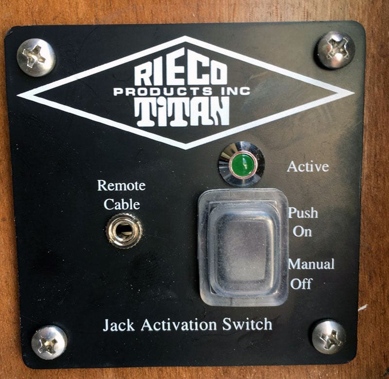
Voila! One jack and slide-out room activation switch is installed.
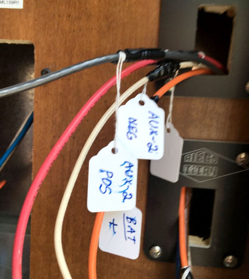
In a previous picture, I mentioned the neat rocker switch feature Rieco-Titan has on their control board. My wire markers had not come in so I used labels to mark the wires for both rocker switches that you see below.
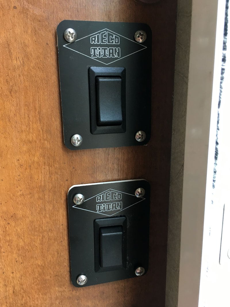
They say a picture is worth a thousand words. The two rocker switches shown above are fully installed and open and close my two slide-out rooms.
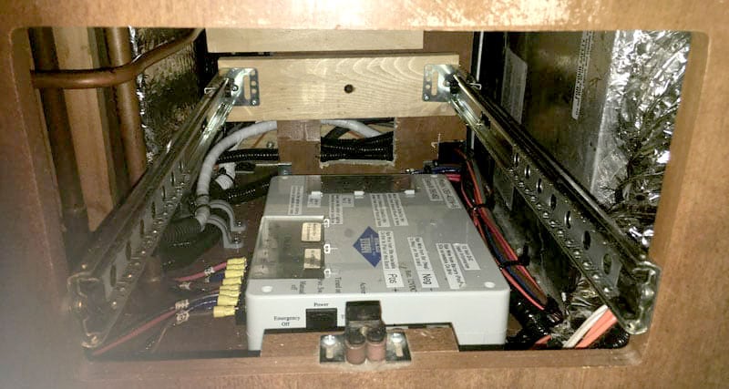
Pictured above is the fully wired Rieco-Titan control board.
The reason I picked this location is that all I have to do is remove the storage drawer and I can see all of the LED lights and what is going on.