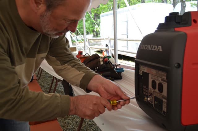
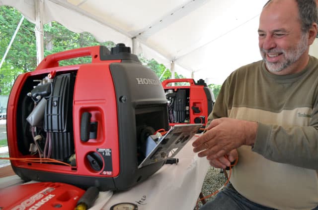
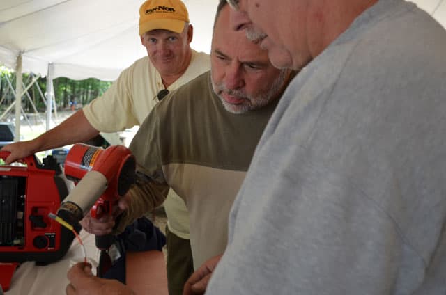
Mike Tassinari, aka Mikeee, shows us how to install an hour meter on a portable Honda EU2000i generator. Look out little red Honda, Mikeee has a drill.

Mike Tassinari frequently offers newbie and technical seminars at his North-East Truck Camping Jamborees. At the Mid-Atlantic Truck Camper Rally this past year, Mike offered a newbie seminar on truck camping basics including how to maintain truck camper water heaters, refrigerators, and air conditioners. At other Jamborees, Mike hosts truck camping safety seminars and checks camper smoke alarms and propane compartments.
Essentially, Mike is a walking and ever talking hands on technical encyclopedia of truck camping knowledge. Lucky for us, he also happens to work for Klondike Bars. What would Mikeee do for a Klondike Bar? You’re about to find out.
This past May, Mike offered a “do it yourself” seminar at the annual Lobstah Bash Jamboree on how to install an hour meter on a portable Honda generator. Honda EU2000i generators have become a standard in the truck camping industry and community and we personally prefer them to built-in generators for their efficiency, quiet operation, and versatility. Mike’s seminar revealed one more advantage of the Honda EU2000i, easy maintenance. And with his hour meter modification, the maintenance gets even easier.
Below is the step-by-step process showing the installation on Guy Dalphond’s Honda EU2000i generator. Although this installation isn’t very complex, please do not attempt this modification if you’re not hands-on and technical. The installation may also void your Honda warranty.
Thank you, Mikeee!
By Mike Tassinari

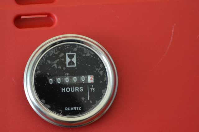
Above: The hour meter helps you monitor the hour usage in portable generators
The easiest way to monitor the hour usage for my new Honda EU2000i generator was to install an hour running meter. After a bit of poking around inside the Honda EU2000i, I found very few places to mount one physically inside the unit. I decided that the easiest way to install an hour meter was to mount one on the service access cover.
An hour meter works by using D/C current to power a tiny motor inside the hour meter, thus turning the numbers on the dial.

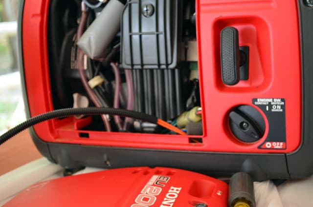
Above: Before the hour meter is installed on a Honda Generator
Since my preliminary investigation of my Honda showed an easy way to get that D/C current via the D/C charging circuit on the front of the generator, I knew that was where I was going to install my wires to power up the hour meter.
Part 1 – The Hour Meter Wiring

 |
 |
 |
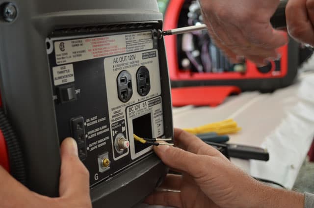
1. Remove the four screws that hold the faceplate of the Honda generator.
 |
 |
 |
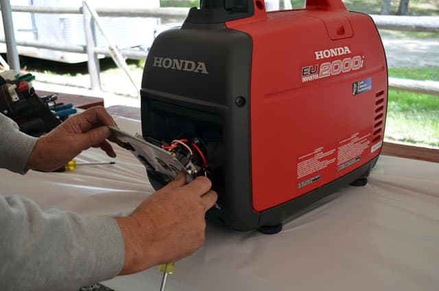
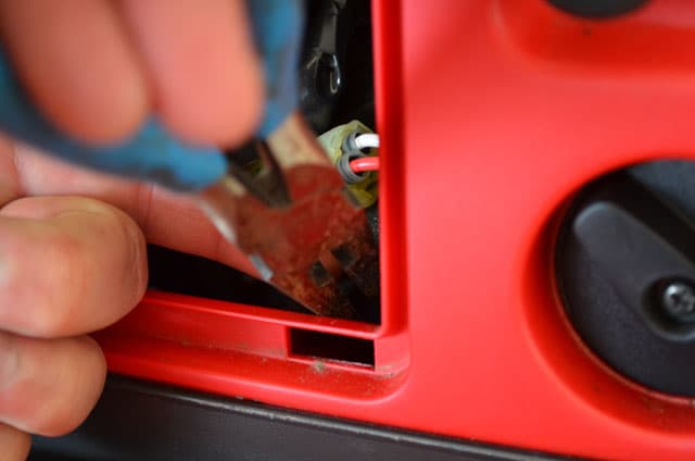
2. Lift the face plate up and out to reveal all the wiring behind that face plate. The object is to get at and remove the D/C 12 volt, 8 amp charging module, so we can tap off those two wires and feed our hour meter.
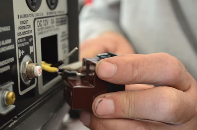
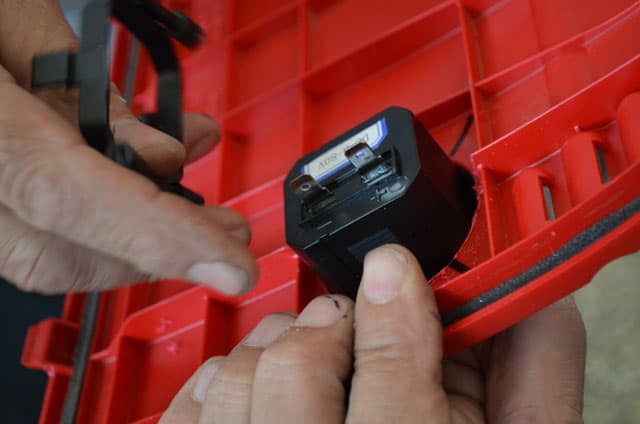
3. To remove the charging module component from the face plate you will have to push in the four corner tabs while gently putting pressure from the back of the module towards the front.

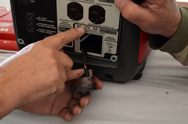
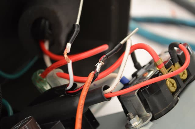
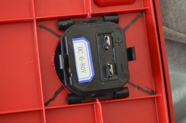
Above: The 8 amp charging module, look close on the module and you will see a + (positive) and a – (negative) where the factory wires are clamped in place

Above: Mikeeee’s writing of the wire color code on the table cloth; white means white wire with red stripe (see picture below)
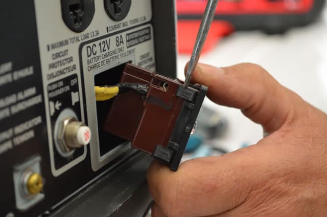
4. Before you attempt to remove the wires from the D/C 12 volt, 8 amp charging module, look close on the module and you will see a + (positive) and a – (negative) where the factory wires are clamped in place. Write down the wire color that goes to the negative and write down the wire color that goes to the positive. The reason for taking note of the wiring color code is to make sure the positive goes back into the positive hole and the negative goes back into the negative hole.

Above: The wires disconnected from the D/C 12 volt / 8 Amp charging module
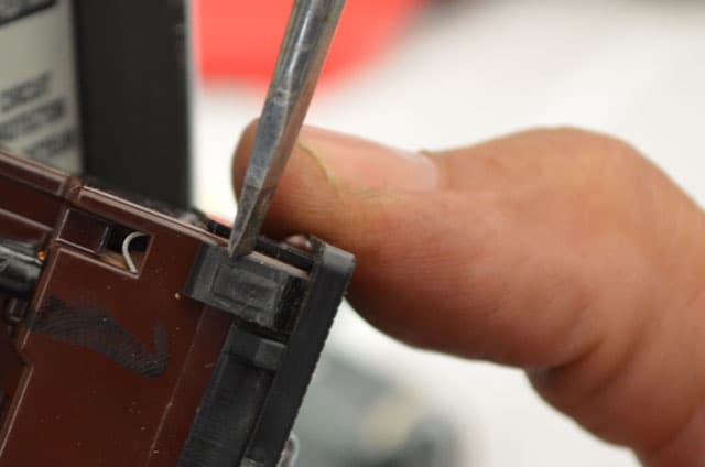
5. To remove the wires from the D/C 12 volt, 8 amp charging module, you need to slightly push in those metal tabs next to each wire. While pushing in on the tab, slightly pull at the wire and it should come out easily. You have now easy access to the positive and negative wires. It is these wires that you are going to “tap” into power up the hour meter.
For this demonstration, I used an American Wire fourteen gauge wire to power up my 12 volt D/C hour meter. That is overkill in regards to the wire gauge, but I had an entire spool of this 14 gauge wire, so why not put it to good use.

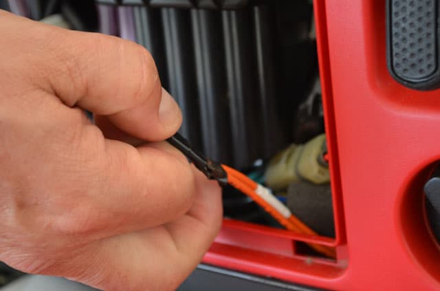
Above: Skinning back the insulation; copper wire showing above with half inch of insulation missing
6. Now comes the tricky part. You want to skin back the insulation of each wire, but not damage the copper wire itself. Ideally you want between ½ and ¾ inch of copper wiring showing.

Above: The 36” of length and marked with white tape
7. You will need to cut two wires. I did 36” of length and marked one of them with white tape so that I will be able to identify one length of wire from the other. I then made a metal note that the wire with the white tape was going to be my negative wire.
8. Now that you have skinned back the insulation on the two wires feeding the D/C 12 volt and 8 amp charging module, it is now time to install the wires that are going to feed the hour meter. I also determined that the wires had to be protected from chaffing and bought some ¼” protective wire wrap.
 |
 |
 |
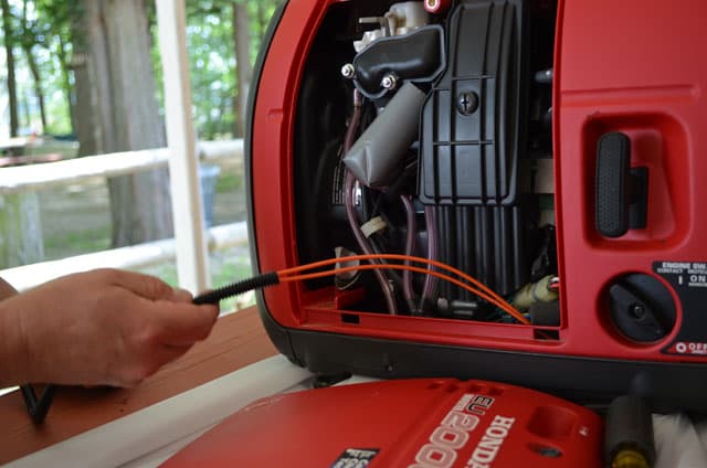
9. The easiest way to get the wiring and its protective wrap from the front of the generator to the side access door is to do it in two steps.
First, tape the two wires together. Do not put the wire in the protective wrap at this point. Using a flashlight, you will see a small place on the lower left, down low behind the generator face plate, where you can push the wires towards the access door. Getting these wires to the side access door may take a bit of trial and error, but it can be done relatively easy.
Keep a flashlight handy and at some point you will see the wires that you have pushed from the front of the generator. Once you see the wires at the bottom, use needle nose pliers to grab the wires.

Above: The Protective Wire Wrap in the photos below covering the wires to power up the hour meter
 |
 |
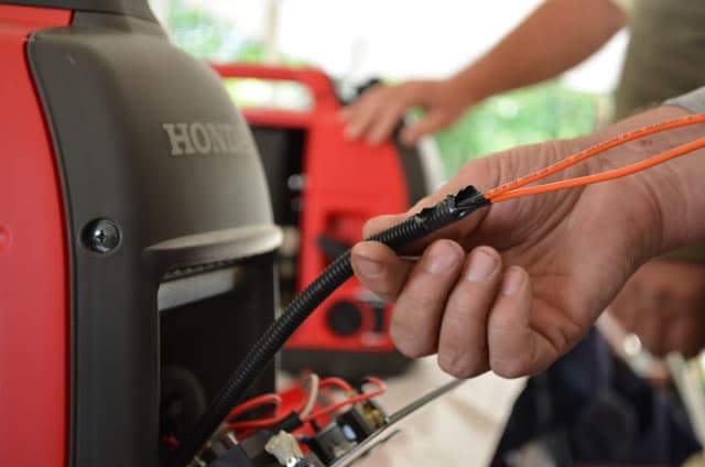 |
10. The second part is to slide the protective wire wrap from the side access door towards the front of the generator. You want to leave about five or six inches of wire, beyond the protective wrap to make your connections.
 |
 |
 |
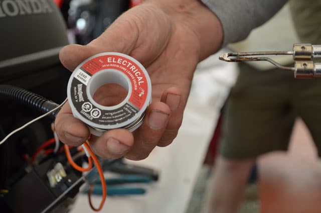
11. The only way it to make a secure connection is to actually solder the new wire on the skinned back insulation of the D/C 12-volt 8-Amp charging module wires.
Note that I designated the wire with the white tape as my negative (-) wire and the non-marked wire as the positive (+) wire. Solder both wires on to D/C 12-volt 8-amp charging module wires.
 |
 |
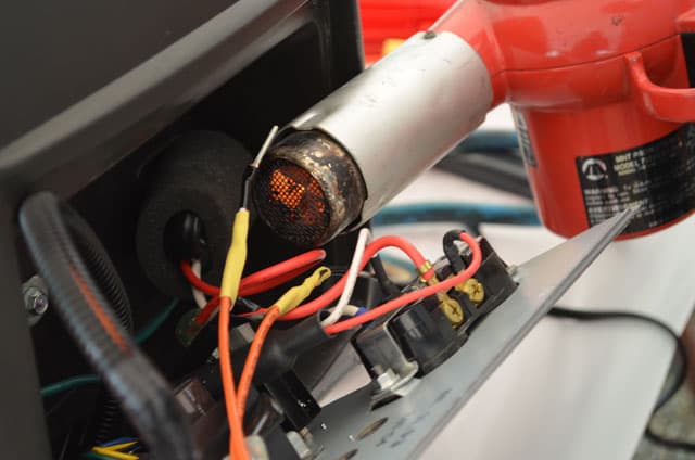 |
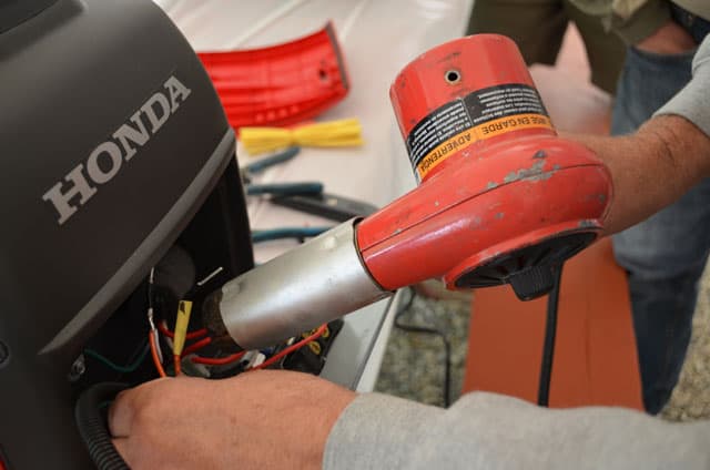
Be very, very careful when using this heat gun to shrink your tubing. Specifically, you do not want to damage any of the surrounding wires.
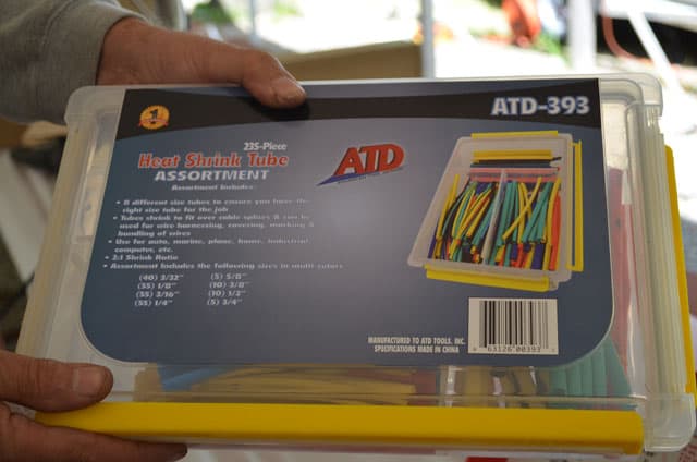
Not everyone is going to have a electrical heat shrink tube kit. It is okay to use a good quality electrical roll of tape to cover the soldered connections. I wanted to do a better job of sealing these connections and just happened to have this heat shrink tube assortment available. So I picked the right size and cut it to length. Then, I just slid the shrink tube over the bare wires and made sure I did not see any bare wire. Please note that a house hold hair dryer does not generate enough heat to shrink the tubing. You need something like a heat gun.

Above: The tie wrap to hold the everything in place
Before you begin to put the D/C 12-volt 8-amp charging module back in place, I used a tie wrap to hold the protective wire wrap and wire in place.
 |
 |
 |

13. Make sure you put the original wires from the D/C 12-volt 8-amp charging module in the correct wiring slots. Positive wire to the (+) mark on the module body and the negative wire to the (-) mark on the module body.
14. Pop the D/C 12-volt, 8-amp charging module back into the face plate. Then put the face plate of the EU2000i back into position and secure with the four screws.
Part 2 – The Hour Meter Hole on the Honda EU2000i Generator Compartment Door
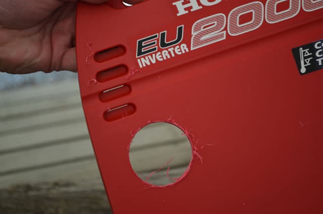
The hard part is done and the rest is a piece of cake. At the beginning of this article, I talked about using a round hour meter because of the location I wanted to put it in. All that is left is to make a hole in that access cover and install the meter.
I also like this hour meter because it has a gasket. Once put through the hole and clamped in place, the gasket gives you some protection against water penetration into the access compartment.
Now the physical depth of the hour meter is 1 1/2 inches, not counting the ¼” male electrical spades sticking out beyond the back of the body. You need to make a hole in your Honda access cover that will give you this depth clearance. The only place with this depth is to the left of the Honda air filter.
 |
 |
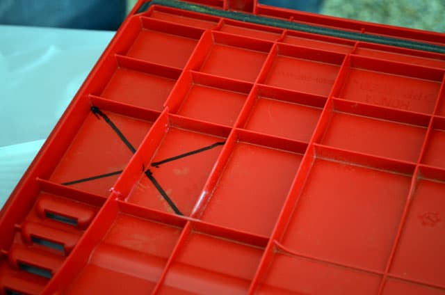 |

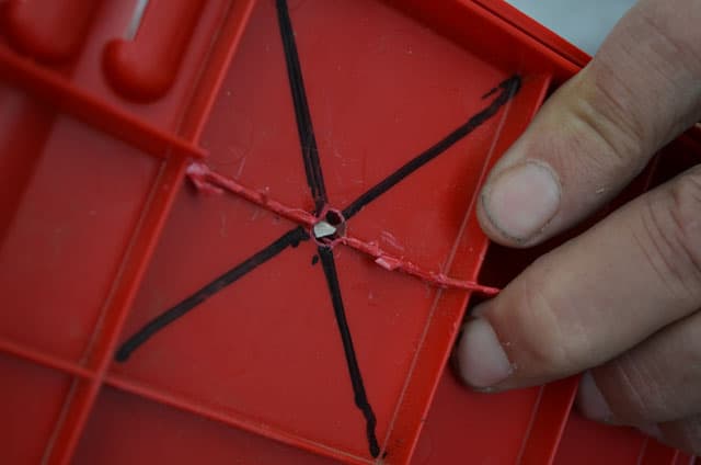
Above: Cutting away the plastic strips on the back of the access cover
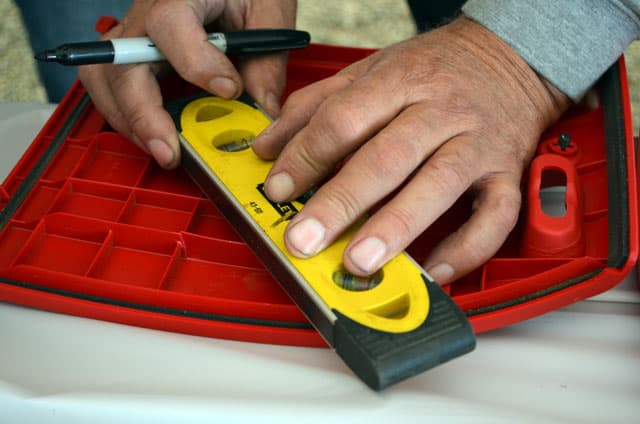
15. Make an “X” with a magic marker, going corner to corner as shown in the picture. You will need to cut two strips of plastic out of the rear of your cover to ensure you find the center of the space you are cutting a hole in.
16. The “X” is to provide the center of where you are going to drill a pilot hole then follow up with the larger hole for the hour meter.
 |
 |
 |
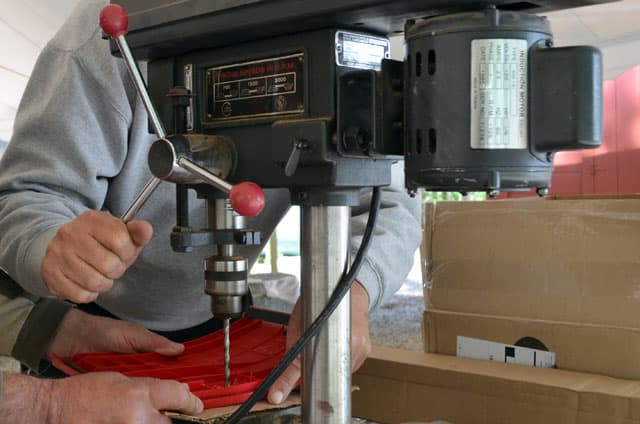
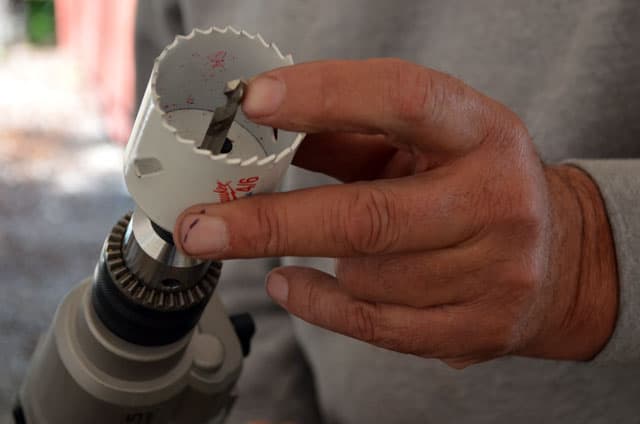
Please note: You will see a picture of my table top drill press and can do both the pilot hole and the larger 2” hole with a hole saw kit. I own two hole saw kits and accidentally grabbed the wrong hole saw kit on the way to the jamboree seminar in the photographs. I had to borrow the campground’s ½” drill to make the larger hole.
17. You have marked the “X”. Now use a ¼” drill bit to drill from the back of the cover directly in the center of the “X”.

Above: The cold weather silver insulation
Please note that if you have a Honda EU2000i generator with the cold weather silver insulation visible (directly to the left of the air filter) you will need to move that pilot hole ½” to the left of the center of the “X” for the hour meter body to clear.
 |
 |
 |
 |
 |
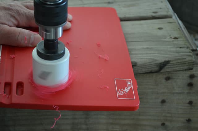 |
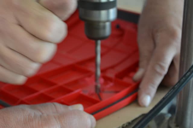
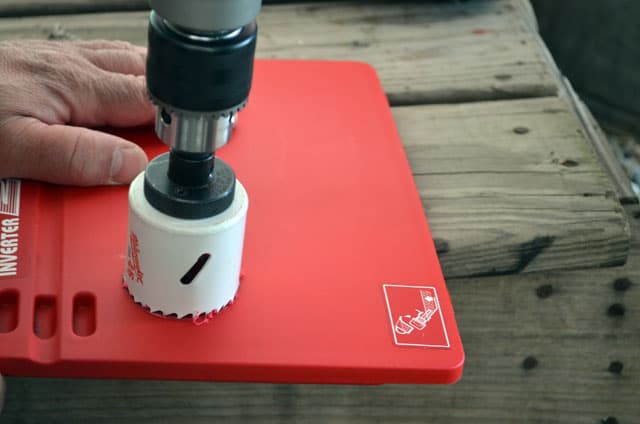
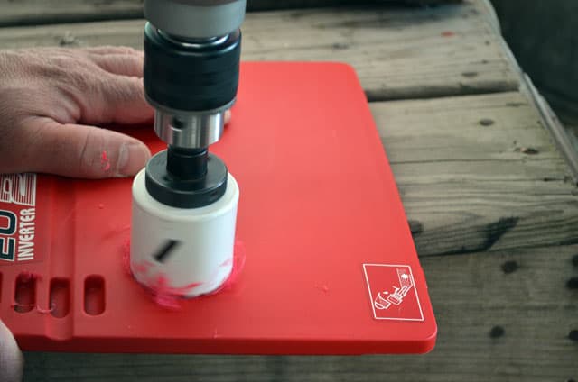
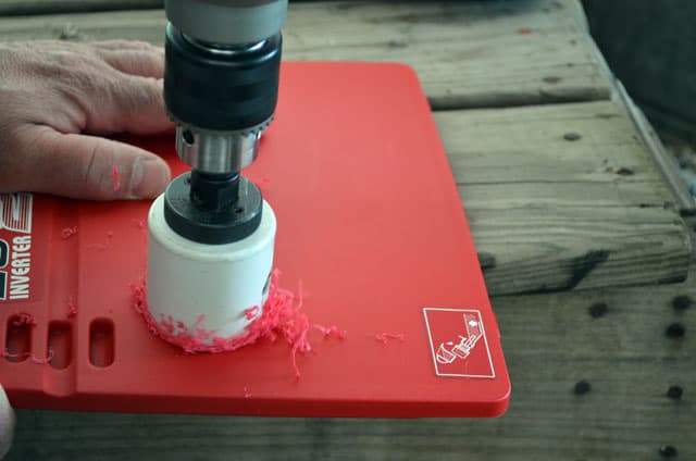
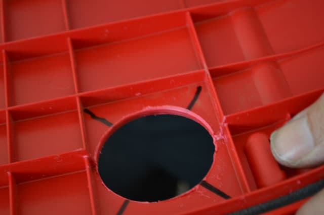
18. Now that you have a pilot hole established, you can proceed to drill the larger hole from the front towards the back. You will need a 2” hole saw as that is what it takes to fit the hour meter.
I recommend drilling this larger hole from the front of the cover to the back to have a nice smooth surface for the Hour Meter Gasket to sit against. You will get some burrs at the back of the cover and these can easily be removed.
Now I realize not everyone owns or has access to a drill press. An electric drill will do the job.
 |
 |
 |
Now remove the locking back plate clamp from the hour meter.
 |
 |
 |
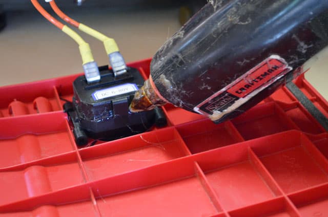
Then slide the hour meter in place and slip the locking back plate clamp back on the body of the hour meter until it’s tight. If you have a glue gun, you may want to drop a dollop of glue in the locking tabs just as bit of insurance the keep that locking back plate in place.

 |
 |
 |
19. At this time you can also work on the other ends of your wires. These wires are going to connect to the hour meter.
Cut about a one inch length of heat shrink tubing and slide it over each wire. Then add the ¼” female solderless connection and crimp. Slide the heat shrink tube over the crimped solderless connector and use heat gun to shrink the tubing accordingly.
 |
 |
 |
Once the hour meter is locked in place, all that is needed is to put the wire on the proper ¼” tabs. The back of the hour meter is marked positive (+) and negative (-). In my example, the wire with the white tape goes on the negative (-), and the other wire goes on the positive (+). Above you can see that I used a glue gun to glue the locking back plate to the body of the hour meter just in case the vibration from the Honda generator somehow unclips that backing plate.

Now you will have to bend the entire solderless terminal and the ¼” tab sticking out to the rear of the hour meter towards the left to clear any obstruction it may hit. After a few tries at slightly bending these tabs until the access door closes easily, you are finished.

Above: Guy Dalphond with his installed Honda EU2000i generator hour meter